重型并串式液压机械臂建模与simscape仿真
一、建模
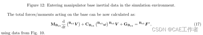
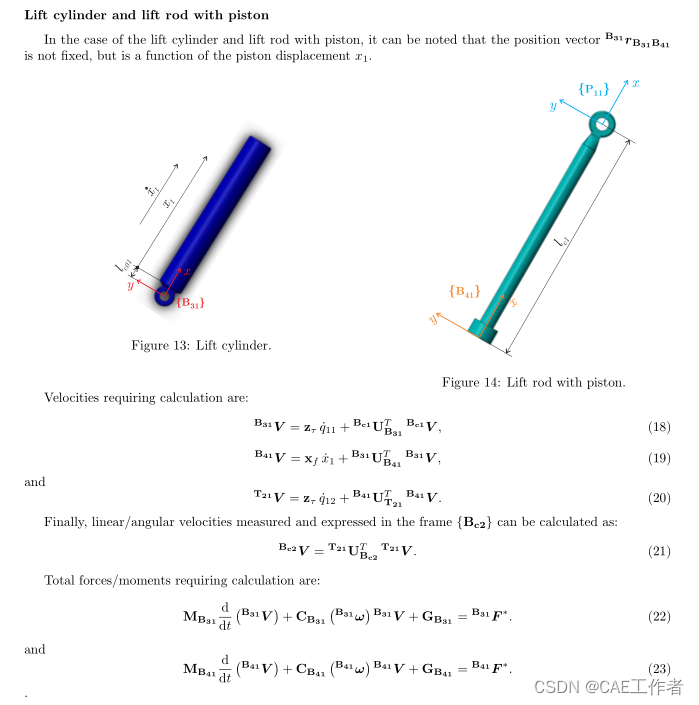
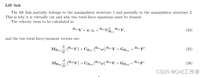
Hydraulic manipulator
Figure 1 shows different constituting parts of the manipulator considered, with every part labeled using numbers from 1 to 10. For each part, a CAD model is provided. Each file is named in accordance with the corresponding label in Fig. 1 and file names are: 01 BaseGP.STEP, 02 LiftLinkGP.STEP, 03 LiftCylGP.STEP,04 LiftPistGP.STEP, 05 TiltCylGP.STEP, 06 TiltPistGP.STEP, 07 TiltLinkGP.STEP, 08 ExtCyl1GP.STEP,09 ExtPist1GP.STEP, 10 ObjectGP.STEP, respectively.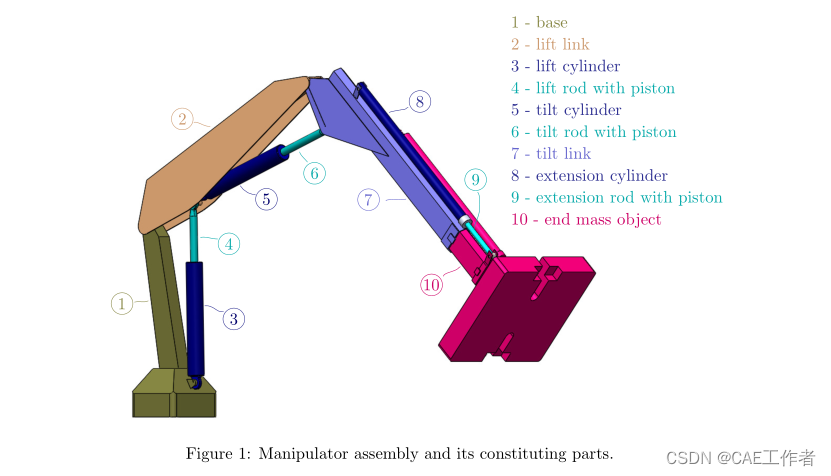
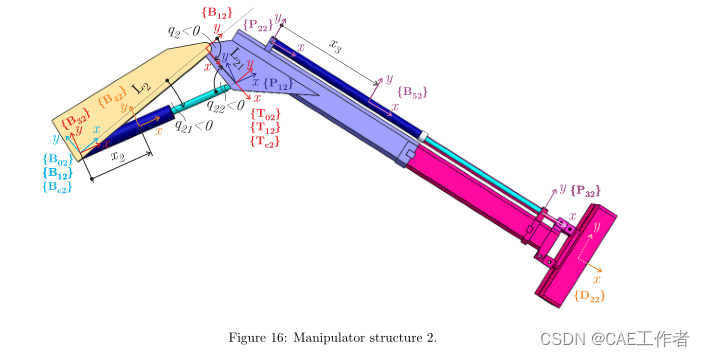
Figure 2 shows the manipulator, conceptually divided into structures in series, as proposed in the paper.The considered manipulator can be divided into two generic manipulator structures. Structure 1 contains onlyrevolute segment, and structure 2 contains both revolute segment with passive revolute joint actuated by a linear hydraulic actuator and prismatic segment with prismatic joint, also actuated by a linear hydraulic actuator.
Figure 3 shows the chosen set of generalized coordinates used both in the following analytic expressions and in the Simscape to command the manipulator motion.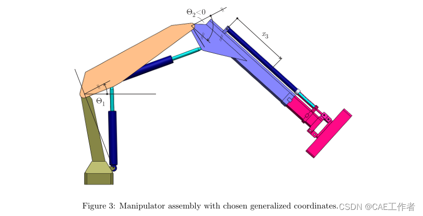
Manipulator structure 1
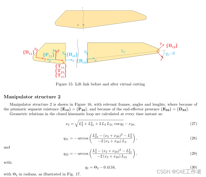
Manipulator structure 1 contains only the revolute segment from Fig.4 − 5, where the notation is inaccordance with the one proposed in the paper. Figure 5 shows the revolute segment 1 with required frames foraddressing the kinematics and dynamics. Since there is no prismatic segment, and a revolute segment follows,frames {E11} and {Bc2} are coincident, {E11} = {Bc2}, and frame {P21} does not exist in the structure 1.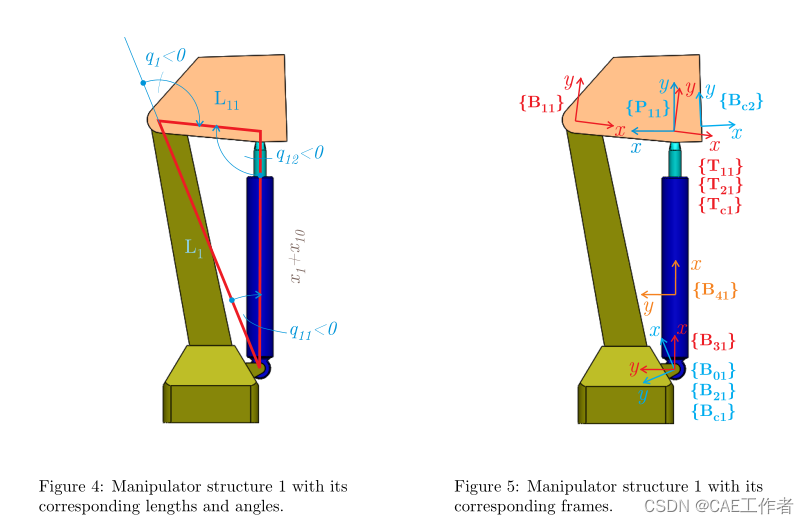
Revolute segment in the manipulator structure 1
It is assumed that linear/angular velocity vector Bc1V is known from previous calculations. Assuming fixed base, this vector is zero vector, Bc1V = 0. All the fixed distances and angles are assumed to be accurately known from CAD models and thus all the constant position vectors, as all the constant rotation matrices.
In addition, all inertia tensors and masses required for dynamics calculations can be obtained from CAD software. Exact numerical values can be found in the attached MATLAB initialization file.
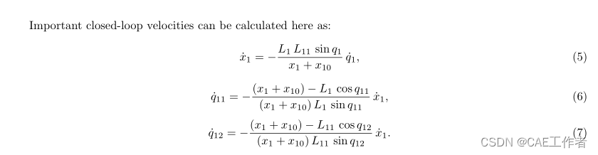
Loop-closure functions
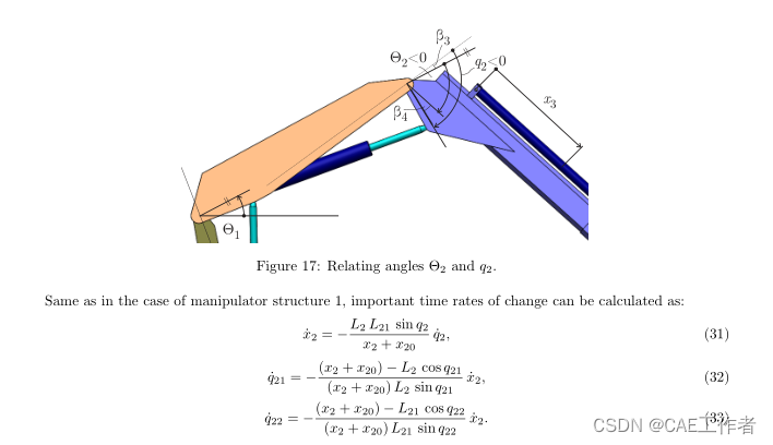
Geometric relations in the closed kinematic loop are calculated at every time instant as: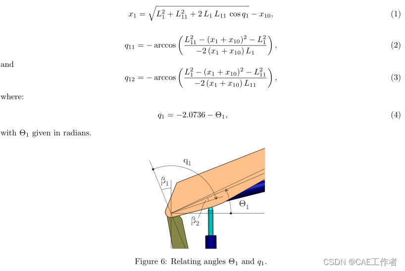
The rationale behind Eq. (4) comes from Fig. 6, with values for β
1 and β 2 found from CAD software asshown in Fig. 7 and defined in the initialization file.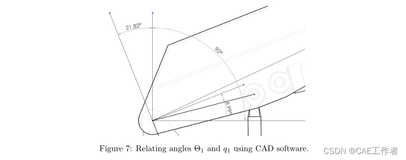
Manipulator base
The manipulator base is shown in more detail in Figure 8 with all the relevant attached frames.
Many
appropriate steps required in the modelling process will be emphasised in the manipulator base case since it is
the first to be considered. The reason for this is to avoid unnecessary repeatability, which would not introduce
much new information. The same approach, shown in more detail once, can be then later applied in the case of
every manipulator part.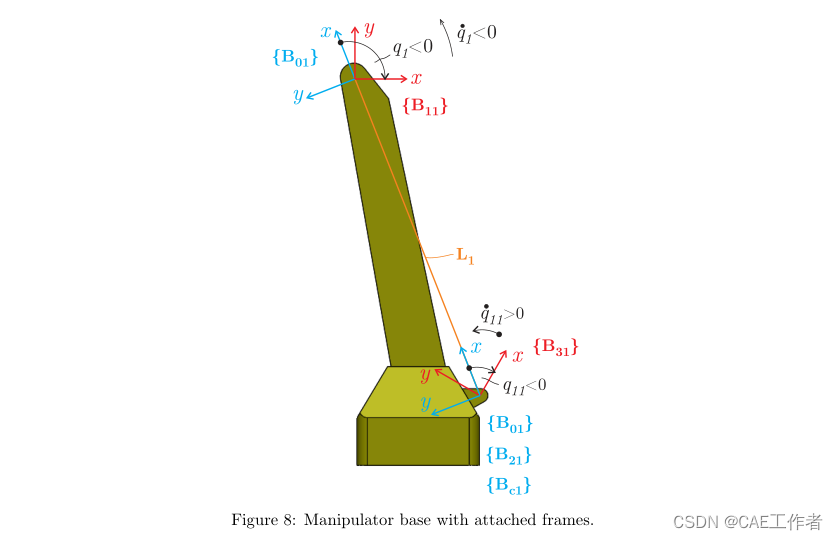
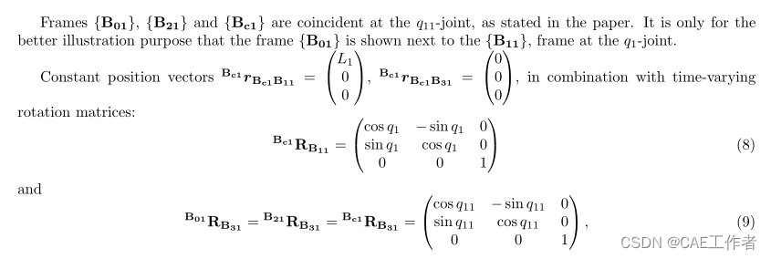
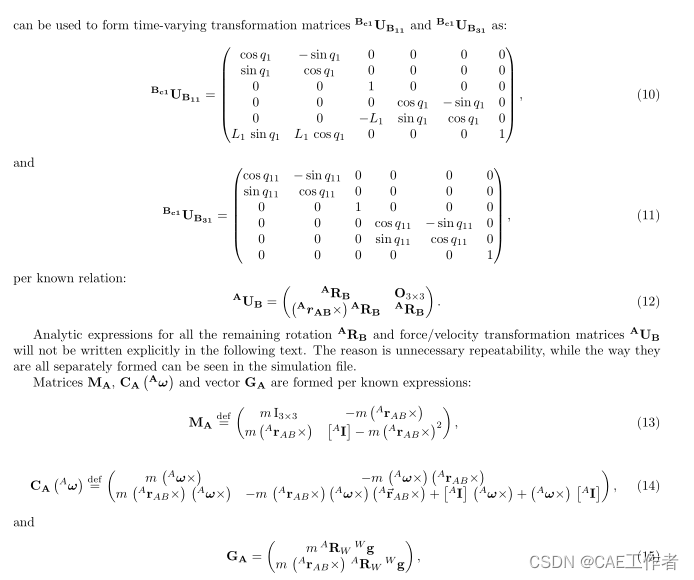

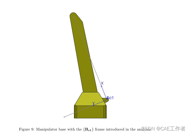
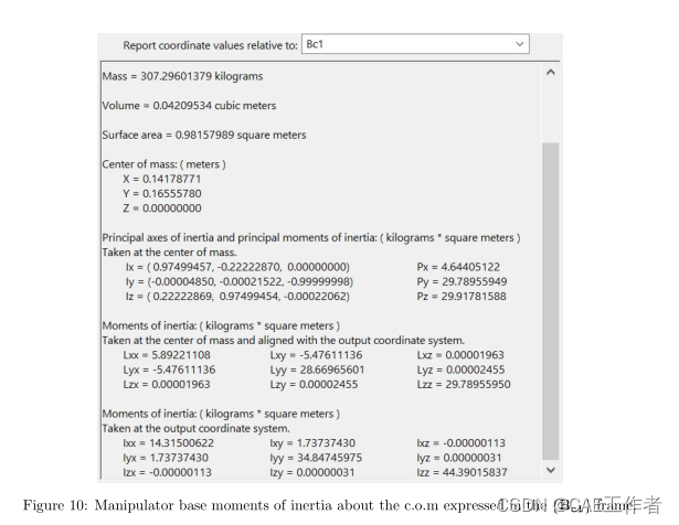
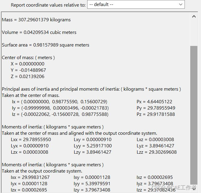
Figure 11: Manipulator base moments of inertia about the c.o.m expressed in the CAD model reference frame.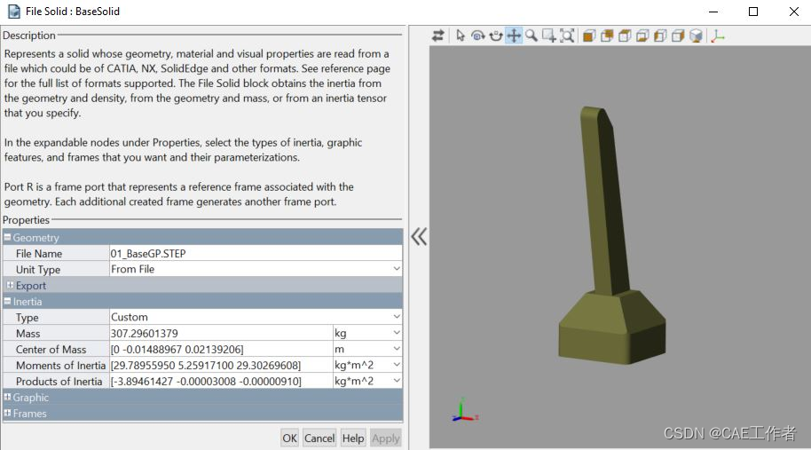
二、simscape仿真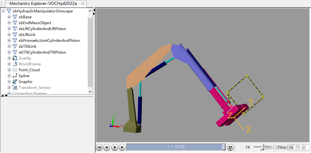
仿真视频如下:
液压控制机械臂simscape仿真
以下内容为付费内容,请购买后观看
1人购买
重型并串式液压机械臂建模与simscape仿真


![ANSYS/ABAQUS使用(带孔平板拉伸实例)[初识有限元CAE分析]](https://img.jishulink.com/cimage/0c683776c596fd2f7dde46fd773a666b_cdn.jpg?image_process=resize,fw_576,fh_320,)


工程师必备
- 项目客服
- 培训客服
- 平台客服
TOP


